Heads and Cam Install Guide for a 1994 LT-1
written by Alex Afrashteh
Before you start, these are the things you will need :
- 10 quarts of dino oil (do not use synthetic for initial startup)
- 5 quarts of your preferred oil (for use right after install)
- 3 oil filters (2 standards, and 1 of your favorite)
- 2 gallons of coolant
- 2 gallons of distilled water
- 2 head gaskets
- 2 intake manifold gaskets
- 2 exhaust manifold gaskets
- 2 water pump gaskets
- 2 TB gaskets (one for TB itself and one for IAC)
- 2 water pump O-ring seals
- 1 timing cover gasket kit
- RTV sealant
- Thread sealant
- Antiseize
- Loctite (medium grade)
- Liquid wrench (spray type is better)
- Assembly lube (necessary for lifters, cam, pushrods, and rockers) - should come with cam
- Harmonic balancer puller
- A longer bolt that matches the crankshaft bolt (preferrably high grade tempered steel).
- Crankshaft sprocket puller and installer if you are replacing the crankshaft sprocket.
- Water pump driveshaft puller and installer if you are replacing it.
- GM fuel rail disconnect tool.
- Torque wrench - you don't need higher than 70 ft. lb. (in. lb. and ft. lb., but you can get away with just ft. lb.)
- Fender covers. You may also want to get quilts to cover more area.
- Comprehensive tool kit with swivel attachments for socket wrench.
- Helms manual - about $90. An absolute MUST.
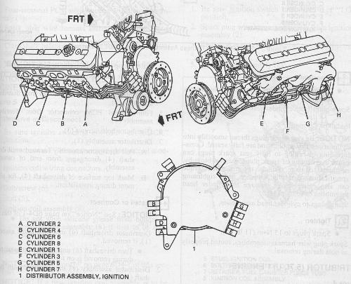
These are two large diagrams of the top-end and bottom-end of the engine that will be of help during the install.
I will leave the install guide up only for reference. I think the best thing to do with this page
is use it for advice. The LT-1 can be disassembled and reassembled many different ways. I'll put
up the tips/advice for the problems that I ran into. Some may seem obvious, but I don't want to
leave anything out.
Tips and Advice :
I recommend you chase all threads (good excuse to buy a quality tap & die kit) and clean all
reused bolts/screws/etc. before reinstalling. Bolts/screws/etc. that will not have anything put
on it (antiseize, loctite, etc.) should be doused in engine oil. This will ensure proper
torqueing and decrease the chance of stripping the bolt/thread.
Take off the hood and jack the front of the car up. Use the left and right side of the cross
member (at the joint) for support. Make sure you use good jackstands, you're gonna be under
the car a lot and you will need to feel safe. If you want to use a creeper, you will need
something that is real low to the ground.
Removal
- Radiator, etc. - The fans rest on the radiator with hook clips. The fans should be removed first
from the bottom. Once the fans are off, you should see that the radiator is actually hook clipped to
the AC radiator. Keep in mind, there are two tranny cooler lines that need to be pulled on the passenger
side.
- Dipsticks - on my car, we did not have to remove the tranny dipstick or oil dipstick. It's not
difficult to get out, but there's always a chance you will bend it when putting it back in.
- Fuel rail - you will need the fuel disconnect tool unless you want to just push the fuel rail aside.
When we were pulling them, it felt like they weren't working, but it just turns out that you need to
press pretty hard in order for the ring to push the metal tabs out of the way. Keep in mind there are
two and they are different sizes.
- Intake manifold - when removing the intake manifold, make sure you disconnect the tube on the
passenger side. It is mounted on with 2 studs/nuts. I can't remember the size. Best if you stand
in the engine compartment when you do it. Also, watch the oil pressure switch on the back of the
block - we broke it on mine.
- Lifters - keep there orientation and position when you pull them. Mine had 63,000 miles on them
and looked real good, so you will probably want to reuse them.
- Water pump - nothing special here. You will need to remove the AIR and its bracket because one
side of the bracket is mounted on a stud off a waterpump bolt.
- Harmonic Balancer - you will need a puller for this. The Helms manual is deceiving, the harmonic
balancer and hub are stuck together *real* good and most likely won't separate. Make sure you
back the crank bolt out some so you have something to push against when pulling the harmonic
balancer. My car did not have a key for this piece even though there was a moonshape cut in the
crank for one. If you are removing the crank sprocket, you'll see that it has a key.
- Timing cover - be careful when you pull the timing cover. There are two tabs at the bottom half
of the timing cover that hold the lower rubber gasket on the oil pan. Try not to break them. I
broke one and it actually helped me get the cover back on, but see if you can retain them. Use
two large screw drivers (or some sort of wedge) to hold the tabs on. Lowering the oil pan a inch
or so makes this so much easier. When you have it together, I recommend using RTV to make sure you
have a good seal.
- Cam - nothing special here, just make sure you pull it out straight so you don't score the
bearings. You may be able to swivel the AC radiator out of the way, but when we loosened the
fitting and started to turn, the fitting started to leak and one of lines was starting to bend.
You may want to save your energy and just drain the system. It is under a lot of pressure and
there are TWO bleeders, so be careful. If you bleed your AC, pull the AC relay so you don't turn
it on by accident.
- Heads - there is some sort of cooling line that runs on the back of the heads that is bolted on
to each head. Those suckers are on there good, so I recommend you unbolt the heads and take them
off at the same time. When you put them down, don't bend the metal tube! Some have broken the metal
lines and replaced them with rubber tubing.
- Bracket assembly - don't disconnect the PS pump hose as you don't need to move it that much. The
bracket is a pain to work with but it can be messed with. There is no need to disconnect the AC
compressor either.
- Exhaust manifolds - these are a big pain. Make sure you don't lose any of the spacers. It would
be best if you put them back in the same hole they came from (assuming you are not doing headers).
The collector bolts should definitely be soaked in liquid wrench. If you don't, they break and
it's difficult to get them out (we drilled two of them out).
- Make sure you clean the block real good before you start assembling. We used 1500 grit sandpaper.
Get a lot of sheets so you don't run out.
Assembly
- Cam - Before you install the cam, compare it to the old one. Make sure the dowel is on the
correct side. If you have an Opti that is driven by the dowel, the dowel will be long - if not,
the dowel should be short. If it is too long, get the cam in first and mark where you want to cut
with the cam sprocket on. Cutting it with a dremel is the way to go. You will probably want to
deburr the edges after you cut it. When installing the new cam, be generous with the cam lube.
Keep the cam level and use a slight rolling motion when you put it in.
- Sprockets - hang the chain on the cam sprocket and wrap it around the crank sprocket. Line up the
two dots (make sure the chain is sitting in the correct teeth so they do line up) and put the cam
sprocket on. When you do this, spin the waterpump gear a little so that it meshes with the cam
sprocket. Use Locktite on cam sprocket bolts.
- Heads - Put the spark plugs in before you put the heads in (remember to use antiseize). Put the
tubes on the back of the heads and install the same way you pulled them. Make sure you don't move
the gaskets by utilizing the locator pins. Torque those puppies down right! There are two washers
that may not fit because of spring seats. Use a grinder and grind them to fit.
- Wiring - do this before you put the exhaust manifolds on. Make sure to use the metal
sleeves. The stock looms are definitely useful for routing. If you are doing headers, you'll
probably have to put the headers on first, then do the routing.
- Timing cover - I made a conceptual mistake when preparing for the timing cover. I thought the
two O-rings for the waterpump driveshaft were the pieces that would tear - wrong. The water pump
driveshaft seal on the timing cover is what gets ripped up! This should be installed *after* the
timing cover is on (and I recommend you use the stock one). Installing the timing cover with the
oil pan gasket on right is another story. Some have been able to do it, but I had to lower the
oil pan in order to get the clearance I needed to get it on right. On the driver's side, you'll
need to disconnect the oil cooler lines (if you have one) to get access to the bolts. The
passenger side has a bracket for the tranny cooler lines in one of the oil pan studs. Once you get it
off, swivel it and push it out of the way. Most of the bolts are 3/8", make sure not to back
the bolts out all the way. Lightly pry the oil pan from the front to get the access you need.
When the cover is on, I recommend you use a healthy amount of RTV where the two tabs were to
ensure a good seal.
- Optispark - not too big of a deal. With the '94, you can't put the thing on right unless it's
lined up right. Don't force it though.
- Harmonic Balancer - you will not be able to install the balancer with the stock crank bolt. I had
to go to the store and get the same bolt, just longer. I also made sure it was higher grade.
Use oil on the crank and inner lip of the harmonic balancer to help matters. Also, don't forget
to oil the seal on the timing cover. This is important as you could burn it up on startup if it
is not prelubed. Use your bolt (with spacers if necessary) to pull the balancer back on. Go
slowly and don't force it if it isn't going on. Also, make sure the arrow points up so that you
know where TDC is (this assumes the dot on the crank sprocket was either pointing up or down).
- Water pump - don't forget the two O-rings. Also, keep in mind that one of the bolts is studded
and the stud is used to help mount the AIR pump. Use RTV on the gaskets to hold them and ensure
a good seal. The top locators on the timing cover will help you put the water pump on.
- Rockers - The CC Pro Magnum rockers I got had grooves in them so that they could be locked
down correctly. You will know what I mean if you have them - when you try to tighten down the
locking screw (allen), it will go in too far. If this is the case, it means the rocker in on
upside down. Use the instructions in the manual below to adjust your rockers. The manual says
1 turn past 0 lash. I went with 1/2 turn past 0 lash.
- Valve covers - I had to modify mine to get them to go on. They were a tight fit, but cutting
into the supports did the trick.
- Intake manifold - there are a lot of little things on the intake manifold. If you got a new one,
make sure to transfer ALL the parts over, including the fittings. The Felpro gaskets I got had
plastic locators for the intake manifold gaskets - very helpful. Before you put the manifold on,
make sure you put down a healthy bead of RTV on the front and back of the block. Extend them up
about an inch to the heads. Watch the oil pressure switch when you put it on.
- Fuel rail - You needn't remove the clips that hold them to the rail, they come all together
(rail and injectors) off the intake manifold. You will need to push them back in to the manifold.
If you have to force them in, you're not doing it right. Try oiling the o-rings.
- Exhaust manifolds - definitely a pain. Make sure you use the spacers and get the studded bolts in
the right places. The gaskets for mine had to be slightly cut.
- Radiator, etc. - do the reverse of disassembly. AC first, then the radiator. Make sure you don't
miss any of the clips. Once they are in, the fans go in from the bottom. There is also the
electrical connections, the tranny lines, and the AC lines.
- Everything else - it does go together relatively intuitively, but having another car to base off
of is important. Get some people involved who have LT1 engines! Double check your wires and check all
the hoses to make sure they are in.
Manual
Disassembly
- Let the car cool for a few hours, your hands will thank you.
- Take off the hood and store it somewhere safe.
- Draining Coolant :
- Remove coolant reservoir cap. (Note : There can be pressure build up, so be careful)
- Lift drive belt tensioner assembly downward (counter clock) off drive belt and remove serpentine belt.
- Drain radiator using radiator drain cock assembly. (Refer to diagram )
- Open both bleed vents. (Note : If you are reusing your Optispark, be very careful not to get it wet)
- Remove drain hold plug and knock sensor located on both sides of engine. This will drain the block.
- The coolant can be saved or disposed of properly. (please : not the drain)
- Jack up front of the car. Block off rear tires. Put car in Neutral with parking brake. (Note: You may want to jack up at all 4 corners)
- Drain engine oil and remove oil filter.
- Relieve fuel pressure by opening fuel cap.
- Removing radiator and accessories :
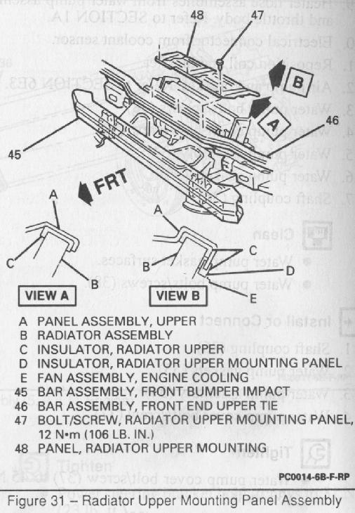
- Remove radiator air upper baffle assembly. (Refer to diagram)
- Remove entire air intake system up to throttle body. Don't forget to disconnect the IAT.
- Disconnect fan wires and remove fans from radiator (from bottom).
- Disconnect transmission oil cooler lines.
- Disconnect electrical connector at coolant level sensor (under waterpump) and remove sensor.
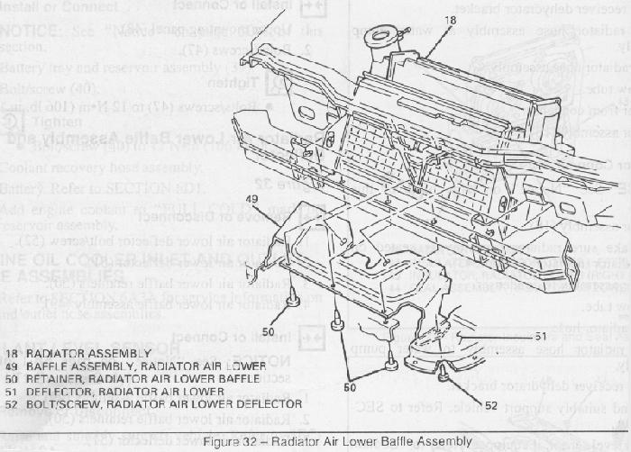
- Remove radiator air lower baffle assembly deflector. (Refer to diagram)
- Remove radiator air baffle assembly. (Refer to diagram)
- Remove hose from radiator to thermostat housing.
- Remove hose from water pump to radiator.
- Remove hoses on TB.
- Remove radiator/fans from top of car (four clips).
- Removing the intake manifold :
- Remove battery.
- Remove alternator and alternator bracket.
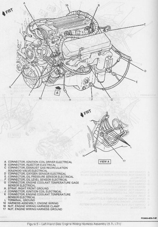
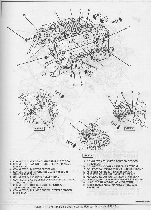
- Detach wires. (Refer to diagram & diagram)
- Remove wiring harness to injectors (they are labeled).
- Left and right wiring harness.
- Remove accelerator cable bracket bolts/screws, bracket & cables from TB.
- Disconnect accelerator cruise control servo cable adjuster assembly.
- Remove secondary air injection diverter valve hose.
- Disconnect fuel pipe connector from fuel rail (use disconnect tool).
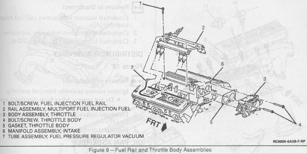
- Remove fuel rail bolts. (Refer to diagram )
- Remove pressure regulator vacuum tube assembly (rubber pipe).
- Push fuel rail aside.
- Disconnect vacuum and crankcase vent hoses. (Note : this is a good time to check the PCV. Shake it, if you feel something inside is moving back and forth, it is good)
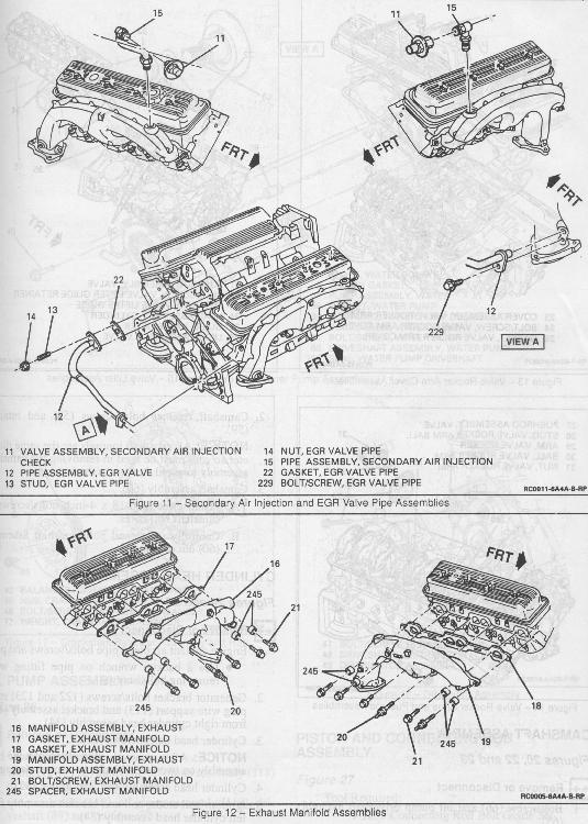
- Remove EGR and it's accessories. If heads are not being pulled, you needn’t disconnect the EGR tube from the passenger side header. (Refer to diagram )
- Remove secondary air injection pipe fitting, nuts, and pipe assembly. (Refer to diagram )
- Remove TB and discard gasket. (Refer to diagram )
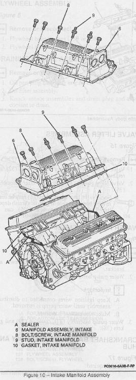
- Remove intake manifold. If reusing bolts, keep them in order. Discard gaskets.
- If you are upgrading the TB, remove all pieces from the old TB. Throw out the IAC gasket as you should have a new one.
- Thoroughly clean intake gasket surface. Doing this right will save you trouble. (Note : Put something in your lifter valley to prevent gasket material from getting into the engine)
- Head preparation for cam removal
- Remove fluid level indicator tube from transmission housing (A4 only).
- Remove brake boost vacuum hose.
- Remove valve covers. (Note : you can most likely reuse the rubber gaskets)
- Remove both valve covers.
- Remove rockers and all the pushrods. If reusing, keep them all in order including the balls and nuts.
- Remove lifter valley guide.
- Remove all lifters and their guides. If reusing, keep them all in order. This would be a good time to inspect them. If you feel that any of them are not good, get a new set or replace that one.
- Remove oil pump driveshaft (one bolt).
- Removing water pump, timing cover, and timing chain assembly
- Remove the coil and its bracket (on driver's side head). Since you are removing it, it's a good idea to replace the coil.
- Unbolt air motor and remove.
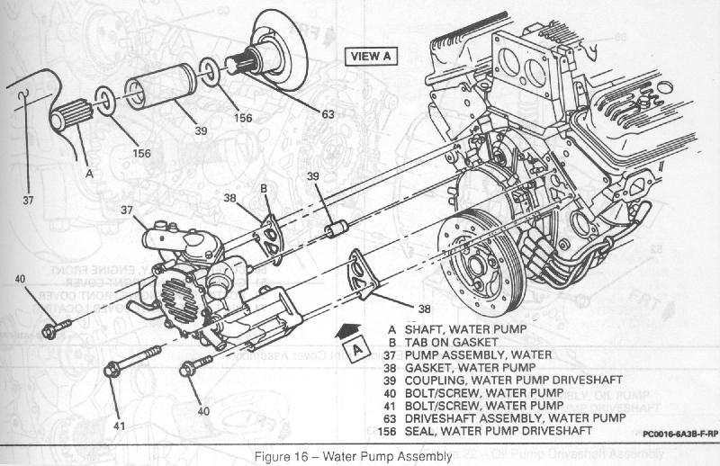
- Unbolt water pump and cover bolts. Remove the water pump. (Refer to diagram ) (Note : If you are reusing the Optispark, make sure not to get it wet)
- Discard both water pump gaskets and clean gasket surface area.
- Remove shaft coupling, discard O-rings.
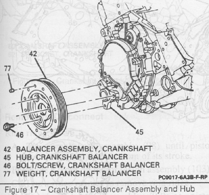
- Unbolt 3 bolts to remove the harmonic balancer. (Refer to diagram )
- Match mark the hub to timing cover. Remove the bolt and washer from front of crank and remove the hub using a hub puller. (Note : you do not have to match mark the hub, there in another way to correctly align the hub on the crank).
- Pull spark plug wires from Opti. For ease of assembly, you can label wires.
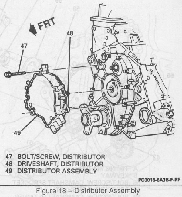
- Pull PCM connector from Opti and pull Opti forward (3 torx screws). Store it in a safe, dry place if you are reusing it. Make sure the Opti driveshaft is not stuck in the cam sprocket, keep it with the Opti. (Refer to diagram )
- If you so desire, loosen some of the oil pan bolts up front and slightly lower the pan.
- Unbolt front timing cover.
- Slowly and gently remove the timing cover. Use special care NOT to break the seal at the oil pan by using some sort of wedge (a large flat head screw driver will work). Discard timing cover gasket. (Refer to diagram )
- If you are not replacing the sprockets, align dots on two sprockets. Try not to turn crankshaft after this is done.
- Unbolt 3 bolts to get the cam sprocket off, rethread them back into the cam. (Refer to diagram for next few steps)
- Remove timing chain (I recommend you have a replacement)
- Remove water pump retainer and use GM tool J39243 to remove water pump gear. (Note : only do this if you are replacing the water pump gear. If you are going to an LT4 timing kit, you may want to consider changing the water pump gear. Many have not and gotten away with it, but for ~$50, it's cheap insurance)
- Use sprocket remover to remove crankshaft sprocket. Remove the key and put it somewhere safe. (Note : only do this if you are replacing the crankshaft sprocket)
- Cam Removal
- Remove cam retainer with torx tool.
- Unbolt AC condenser support assembly.
- Unbolt the mount for the AC dryer (cylindrical can near battery). Slowly unscrew the fitting on the dryer just enough so you can swivel the condenser away. Don't get too worked up, the worst that can happen is you discharge the AC.
- Swivel the condenser away enough to clear room for cam removal.
- Carefully remove cam. Use a rolling motion when you are taking the cam out. Take care not to score cam bearing by keeping the cam level. (Note : You may find it to be a very tight fit. You may need to remove the hood latch to remove/install the cam)
- Swivel the condenser back but do not retighten the fitting. (Note : you may want to skip to the assembly section and read the section about putting the new cam in so you don’t have to swivel the condenser again)
- Driver side head removal (not necessary if you are not replacing heads)
- Remove bolts from y-pipe to driver side manifold. These bolts can be difficult to get off, use WD40 or equivalent.
- Remove coolant air bleed pipe bolt/screw.
- Disconnect O2 sensor cable.
- Remove driver side exhaust manifold assembly. Don't lose the spacers. The Helms manual recommends you put the bolts back in the same places they came from. (Refer to diagram ) (Note : If you still have difficulty with the next steps, remove the Y-pipe too)
- Remove spark plug wires. If reusing, keep there order in harness for ease of installation.
- Remove 4 spark plugs. If reusing, take special care not to drop them.
- Remove coolant temperature sensor connector.
- Remove any other accessories not covered.
- Remove 17 head bolts. If reusing, keep bolts in order.
- Pull head and discard gasket.
- Passenger side head removal (not necessary if you are not replacing heads)
- Disconnect AC compressor rear brace bolt from engine block.
- Disconnect AC compressor electrical connector.
- Unbolt AC and lay aside.
- Remove oil dipstick.
- Remove bolts from y-pipe to passenger side manifold. These bolts can be difficult to get off, use WD40 or equivalent.
- Remove passenger side exhaust manifold assembly. Don't lose the spacers. The Helms manual recommends you put the bolts back in the same places they came from. (Refer to diagram )
- Remove coolant air bleed pipe bolt/screw.
- Remove 2 bolts from PS pump through pulley. Remove or push PS pump aside.
- Remove spark plug wires. If reusing, keep there order in harness for ease of install
- Remove 4 spark plugs. If reusing, take special care not to drop them.
- Remove any other accessories not covered.
- Remove 17 head bolts. If reusing, keep bolts in order.
- Pull head and discard gasket.
- Thoroughly clean surfaces of block. (Note : Put something in your lifter valley to prevent gasket material from getting into the engine)
Assembly
- Cam installation
- Look at dowel on the new cam - Is it the same length as the old one? If not, remove the dowel from the old cam and put it in the new one. Alternatively, the dowel on the new cam can be ground down to the correct length if it is too long.
- Carefully, swivel the condenser up and out of the way.
- Lubricate new cam lobes with cam lube. Be generous with the application.
- Insert new cam. Take care not to score cam bearing by keeping the cam level. When installing cam, use a rolling motion and lubricate journals with engine oil as you insert the cam. Take your time on this step. (Note : You may find it to be a very tight fit. You may need to remove the hood latch to put the cam in)
- Swivel condenser back and retighten fitting.
- Install cam retainer and tighten bolts to 105 lb. in.
- Remove three bolts from cam for later install.
- Install oil pump driveshaft. Torque bolt to 13 lb. ft.
- Heads installation
- Make sure head and block surfaces are clean.
- Install head gaskets. Make sure you get it on the right way.
- Use locator pins to place heads.
- Coat all head bolts with thread sealing compound.
- Thread bolts (17 each) into the heads.
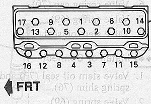
- There is a very specific order to tightening the bolts (see picture below). Tighten them in three sequences to a final spec of 65 lb. ft. (this spec is for stock bolts, if you have new ones, use the spec given by the bolt manufacturer). Don’t fudge this, if you do, you may warp the heads as they are aluminum.
- Bolt up AC compressor. Torque to 24 lb. ft.
- Install coolant temperature sensor (driver side head).
- Connect air bleed pipe assembly and bolts to heads.
- Attach any other connectors to heads that have not been covered.
- Attach y-pipe to both manifolds. If you can, torque studs/bolts to 26 lb. ft.
- Attach both exhaust manifolds using gaskets. Remeber to use the spacers on the correct bolts. Use antiseize on bolts and torque to 26 lb. ft. (some may be difficult to get to with a torque wrench, just do the best you can) (Refer to diagram )
- Install spark plugs. Use antiseize on them. Torque to 11 lb. ft. (Note: if you drop a plug, save yourself the trouble, and get a new one)
- Apply sealant around oil dipstick tube 1/2 inch below bead. Install it into block (rotate into position). Torque bolt to 25 lb. ft.
- Connect O2 sensor cable on driver side manifold. (Note : if you are replacing O2's, use antiseize on them. Make sure you don't get it on the sensor itself)
- Install PS pump. Tighten bolts to 18 lb. ft.
- Put cam lube on the rollers of the lifters and install lifters and guides in the same positions they came from. Presoaking them in oil is also recommended.
- Install lifter valley guide retainer. Torque bolt to 15 lb. ft.
- Installing timing chain assembly, timing cover, Opti, balancer, and water pump
- Install crankshaft sprocket and key (if removed) using installer & mallet.
- Install water pump gear (if removed) using J39092. (Refer to diagram )
- Install water pump retainer (if removed) to 105 lb. in.
- Install camshaft sprocket along with timing chain. Make sure the waterpump driveshaft and cam sprocket mesh. The dowel on the cam must go through the hole designated for it. When it is together, the timing marks on the two sprockets should be aligned (pointing to each other). Turn the crank back and forth to make sure they still match.
- Use locktite on camshaft sprocket bolts and tighten to 21 lb. ft.
- Install new O-ring to water pump driveshaft assembly.
- Now for the hard part - putting on the timing cover. Make sure to use the proper gasket. The hard part is actually getting the timing cover on right and without ripping the water pump driveshaft seal. J39087 can be used to protect it. Other creative methods can also be used - for example, the seal can be installed *after* the cover is on. Some have used other objects to protect it. Put some time into this step, make sure the seal on the cover is good. Take special care with the oil pan gasket. If you don’t feel comfortable, use high temp RTV. (Refer to diagram )
- Tighten the bolts to 100 lb. in.
- Install Optispark. The driveshaft for the Opti has a keyway missing (a missing spline) on each side. Remove the driveshaft and put it into the cam sprocket. Note its position (putting it in 12 o’ clock helps). Now hold the Opti as it would be installed on the timing cover, put the driveshaft in and turn it until the missing spline is in the same position as it was on the cam sprocket. Put the Optispark on the cam sprocket while slowly rotating it in either direction until the keyway on the driveshaft matches the keyway in the sprocket. Make sure not to force it. If you can’t visualize this, don’t worry, you will understand when you see it. (Note : these intructions are for 1994 and 1995 models. On different years, the Opti is driven off the cam dowel) (Refer to diagram )
- Tighten Opti bolts to 106 lb. in.
- Install spark plug wires. Use the picture below for wiring. Double and triple check you got the right order - this is a common area of error.
- If the crank has been turned so that it is not at TDC for piston 1 and you did not match mark the crank to the hub, turn until piston 1 is at TDC. The cast arrow on the hub should be in the 12 o’ clock position (at TDC). Push the hub on as much as you can by hand. Use the hub bolt and washer to force the hub onto the crank. Be careful, you don’t want to strip the thread in the crank. If you feel uncomfortable, get a hub installer.
- Tighten hub bolt and washer to 75 lb. ft.
- Install balancer and tighten bolts to 60 lb. ft.
- Using the two gaskets, install the water pump. The short bolts should be torqued to 31 lb. ft. while the long ones to 33 lb. ft. (Refer to diagram )
- Rocker Arm install
- Check your pushrods for flatness on a piece of glass. Replace if necessary.
- Use cam lube on both ends of the pushrods. Ensure the pushrods are clean (the middle should have no obstructions) and in good shape. If you are using guideplates, your pushrods must be hardened (‘94 and some ‘95 models have them). Install all the pushrods in the same places they came from. Make sure they seat in lifter sockets.
- If you have guide plates and rocker studs that you have not installed yet, do it now. Apply thread sealant to all the rocker arm studs before installing. Torque to 50 lb. ft. (spec does not change if you are using 3/8" or 7/16" studs).
- Apply cam lube to the valve stems (the exposed end of the valve at the top of the springs), the pushrod-rocker contact, and all other moving areas of the rocker arms. Some performance manuals advise pouring some oil on the rockers also.
- Install all the rocker arms. Do not tighten the adjusters just yet.
- Now it is time to adjust your rockers. You will need to be able to turn the crank (in the clockwise direction) to do these adjustments. Turn the crankshaft until the cast arrow on the crankshaft hub is in the 12 o’ clock position and number 1 cylinder is at TDC. Watch number 1 cylinder valves as the crankshaft hub arrow approaches 12 o’ clock position. If a rocker moves as the arrow moves to position, the engine is in the number 6 firing position. The crankshaft must then be turned one more time to reach cylinder number 1 firing position.
- At this position, exhaust rockers 1, 3, 4, and 8 can be adjusted as can intake rockers 1, 2, 5, and 7. While spinning the pushrod with your fingertips, tighten the rocker down until you feel resistance in the pushrod - this is zero lash. Tighten the adjusting nut on the rocker arm an additional 1/2 - 1 turn (or whatever you think is right).
- Turn the crank 360 degrees (clockwise) until the crankshaft hub is at 12 o’ clock again. Adjust exhaust rocker 2, 5, 6, and 7 and intake rockers 3, 4, 6, and 8 as you did in the step above.
- Using the original gasket, or a new one, install the valve covers. Torque the bolts down to 100 lb. in. (Note : There may be interference from the rocker arms - the covers can be slightly modified (cut) to make the rockers fit)
- Installing Intake manifold
- If you are replacing the intake manifold, now is the time to undress the old manifold and transfer the parts to the new one.
- Apply a 5mm (3/16") bead of RTV sealer to the front and rear of the engine block where the intake manifold will make contact. Extend the bead 13 mm (1/2") up each cylinder head assembly to seal and retain the gaskets. GM recommends the numbers just stated, however, you may want to be more generous with the sealer as this is a potential leak zone. Make sure to use a sealer that is designed for high temps. (Refer to diagram )
- With the new gaskets, position the intake manifold.
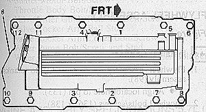
- Tighten bolts in the order shown below. First pass should be 71 in. lb. Final pass should be to 35 ft. lb.
- Make sure the TB is assembled (there is a gasket for the IAC). Install TB with gasket and torque to 19 lb. ft. (Refer to diagram ) If you are going to adjust idle position with the screw, you may want to cut a hole in the gasket where it covers the hole to the adjusting screw. Using the screw should be a temporary solution as the computer will display the SES.
- Install generator and bracket.
- Connect accelerator control/cruise control servo cable adjuster assembly.
- Install accelerator cable bracket. Torque bolts to 90 in. lb.
- Connect secondary air injection pipe assembly. Torque pipe to exhuast manifold bolt to 25 ft. lb. Tighten flange nuts to intake manifold to 19 ft. lb. (Refer to diagram for this step and next)
- Install EGR and valve relay. Torque bolts to 16 lb. ft.
- Connect vacuum and crankshaft vent hoses.
- Connect fuel pressure regulator vacuum tube.
- Put on the fuel rail and torque bolts to 15 lb. ft. (Refer to diagram )
- Connect fuel pipes to fuel rail (clicks in).
- Connect secondary air injection diverter valve hoses.
- Connect left and right wiring harness. (Refer to diagram & diagram)
- Connect wiring harness to injectors.
- Install coil and coil bracket. Use silicone grease on metal mounting face of bracket.
- Install the radiator/fans and attach all hoses.
- Install knock sensor and drain hole plug.
- Make sure the drain cock is closed. Fill system with 50/50 coolant/water to "cold" mark. (Note : leave radiator cap off)
- Put on the serpentine belt and tighten the tensioner.
- Put in the battery (don’t connect).
- Use 5W30 oil. Install oil filter and make sure you add some oil to it for better initial oil flow. Subract the amount of oil added to filter from 5 quarts and add to engine.
- Put on the air bellow and cold air induction (there are some electrical connections).
- Put back the gas cap.
- Open bleed valves and fill radiator with 2 gallons coolant and ~ 1.5 gallons distilled water.
- Install the hood.
- Wait about 4 to 5 hours (good time to take a break and relax). This time will make sure the sealant drys. It will also clear your head.
- Check all connections. Look for anything that may have been missed. Take your time on this step.
- Lower the car from the jacks.
- Connect the battery.
- Fire the engine. When you do, hold it until it fires. Don't let off if it doesn't start right away.
- Hold the RPMs to about 2,000 for a couple of minutes. Competition Cams recommends 30 minutes. Do whatever you feel is right.
- Let the engine warm up. Adding water to the system and closing the bleed valves when coolant leaks would be a good thing to do now.
You’re done! Take it easy on the car for a bit. Watch oil pressure and engine temps closely. Check for leaks.
Change the oil and filter after about 20 minutes of use - this is important so that metal contaminents and the lube that was used doesn’t damage the engine. Change your oil again after a couple hundred miles. After that, it is safe to use synthetic.
After a heat and cool cycle, retorque the intake manifold and exhaust manifold bolts. You may want to do this twice to make sure they are tight. Listen for rocker ticking. Some amount is to be expected, but if it is excessive, you will probably
want to readjust them. Questions? E-mail me at alex@afrashteh.com.